.png?v=v1)
.png?v=v1)
2022.10.21
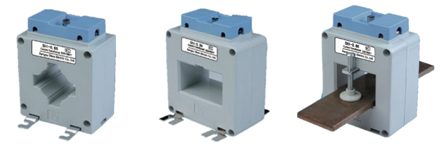
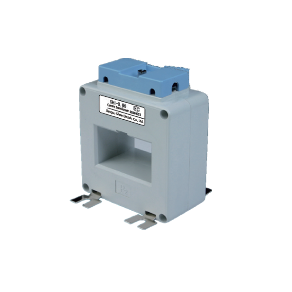
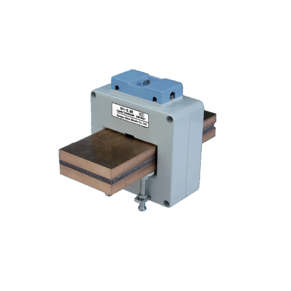
High accuracy current transformer is composed of closed iron core and winding. The number of turns of its primary side winding is very small, and it is connected in series in the circuit of the current to be measured. The number of turns of the secondary side winding is relatively large, and it is connected in series in the measuring instrument and protection circuit. When the current transformer is working, its secondary side circuit is always closed, so the impedance of the measuring instrument and protection circuit in series is very small. The current transformer is used to convert the large current at the primary side to the small current at the secondary side, and the secondary side cannot be opened.

Special Remind
1) Series Connection principle: The primary winding resistance shall be connected in Series with the circuit under test, while the secondary winding resistance shall be connected in Series with all power meter and the other instrument load current transformer
2) Select the appropriate change according to the measured current, otherwise the error will increase. At the same time, one end of the secondary side of the high voltage current transformer must be grounded to prevent the high voltage on the primary side from entering the low voltage side of the secondary once the insulation is damaged, which may cause personal and equipment accidents
3) Open circuit is absolutely not allowed at the secondary side, because once open circuit occurs, all the current at the primary side becomes magnetizing current, causing the iron core to be supersaturated and magnetized, causing serious heating and even burning the coil; at the same time, the error increases after the magnetic circuit is supersaturated and magnetized. When the current transformer is in normal operation, the secondary side is nearly short circuited.
If it is suddenly opened, the excitation electromotive force will suddenly change from a small value to a large value, and the magnetic flux in the iron core will show a seriously saturated flat top wave. Therefore, the secondary side winding will induce a very high peak wave when the magnet passes through zero, which can reach thousands or even tens of thousands of volts, threatening the safety of staff and the insulation performance of the instrument.
4) In order to meet the needs of measuring instruments, relay protection, circuit breaker failure judgment, fault filtering and other devices, multiple secondary winding current transformers are set in the generator, transformer, outgoing line, bus section circuit breaker, bus circuit breaker, bypass circuit breaker and other circuits. For high current grounding system, three-phase configuration is generally adopted; For small current grounding system, it shall be configured as two phase or three phase according to specific requirements
5)The installation location of current transformer for protection shall be set to eliminate the unprotected area of main protection device as far as possible. For example, if there are two groups of current transformers and the position is allowed, they should be set at both sides of the circuit breaker to make the circuit breaker in the cross protection range.
6)To prevent busbar fault caused by bushing flash over of pillar current transformer, current transformer is usually arranged at the outgoing line of circuit breaker or transformer side.
7)In order to reduce the damage caused by internal fault of generator, the current transformer used for automatic regulation of excitation device shall be arranged at the outgoing line side of generator stator winding. In order to facilitate the analysis and find the internal fault before the generator is incorporated into the system, the current transformer for measuring instrument should be installed at the neutral side of the generator.


Current transformer categories
Categorized by measurement principle, current transformers are mainly divided into hollow current transformers, optical current transformers and low power LPCT current transformers.
Categorized by installation mode, it can be divided into: through type current transformer, pillar type current transformer and bushing type current transformer.
Categorized by purpose: measuring current transformer, protection current transformer
Categorized by insulation medium, it can be divided into dry current transformer, cast current transformer, oil immersed current transformer and gas insulated current transformer
Categorized by insulation medium, it can be divided into dry current transformer, cast current transformer, oil immersed current transformer and gas insulated current transformer
Categorized by principle of current transformation: electromagnetic current transformer, photoelectric current transformer
Common faults of current transformer in operation
1. Overheating occurs. The overheating, smoking, glue flow and other phenomena of the current transformer may be caused by poor connection of the primary side wiring, serious oxidation of the secondary side terminal board surface, short circuit between turns in the current transformer or insulation breakdown of the primary and secondary sides.
2. The secondary side is open circuit. At this time, the ammeter suddenly has no indication, and the sound of current transformer increases significantly. Ozone smell and slight discharge sound can be heard near the open circuit.
The hazards of open circuit on the secondary side include:
a. It generates very high voltage, threatening the safety of equipment and operators
b. Iron core loss increases, and equipment may be burnt due to severe heating
c. Magnetic saturation of iron core increases the error of current transformer
3. There is discharging sound or phenomenon inside. If there is discharge on the surface of the current transformer, it may be that the surface of the transformer is too dirty and the insulation is reduced. The internal discharge sound is caused by the reduction of the internal insulation of the current transformer, which causes the breakdown discharge of the primary side winding to the secondary side winding and to the iron core.
4. The internal sound is abnormal. The reasons are as follows: the fastening screws of the current transformer iron core are loose, the iron core is loose, the vibration of the silicon steel sheet increases, and the abnormal sound does not change with the primary load; Due to the poor assembly process of silicon steel sheet, some iron cores have certain buzzing sound during no-load or load stop; When the secondary side is open circuit, due to the magnetic saturation and non sinusoidal magnetic flux, the silicon steel sheet vibrates and the vibration is uneven, resulting in a large noise; The current transformer is seriously overloaded, which increases the vibration sound of the iron core.
5. The oil filled current transformer has serious oil leakage. When one of the above phenomena is found in the operation of current transformer, the load shall be transferred and the power shall be cut off immediately.
Copyright © 2019.Company Name All Rights Reserved.