.png?v=v1)
.png?v=v1)
2021.05.31

1. What is RS485
Industrial field often needs to collect multi-point data, analog signal or switch signal, generally using RS485 bus. RS485 adopts a half-duplex working mode, supporting multi-point data communication. The RS485 bus network topology generally adopts a bus-type structure with terminal matching. That is, a bus is used to connect each node in series, and it does not support ring or star network.
RS485 has no specific physical shape. According to the actual situation of the project, RS485 adopts differential signal negative logic, + 2V ~ + 6V means "0" and - 6V ~ - 2V means "1".
RS485 has two-wire and four-wire connections. The four-wire system can only realize point-to-point communication mode, which is rarely used now. Nowadays, the two-wire system is mostly used. This kind of connection mode is a bus topology structure, which can hang up to 32 nodes on the same bus. The communication distance of 485 bus can reach 1200 meters.
According to the 485 bus structure theory, under the premise of ideal environment, the transmission distance of 485 bus can reach 1200 meters. The condition is that the communication wire is high-quality and up to the standard, the baud rate is 9600 bps, and only one 485 device is loaded, so that the communication distance can reach 1200 meters, so the actual and stable communication distance of the 485 bus is usually less than 1200 meters. If there are many load 485 devices, wire impedance is not up to standard, wire diameter is too small, converter quality is poor, equipment lightning protection is too complex and baud rate is too high, etc., will reduce the communication distance.
2. RS485 cable
Common twisted pair is used in general occasions, and shielded twisted pair can be used in higher requirements occasions. When using RS485 interface, for a specific transmission line, the maximum cable length allowed for data signal transmission from RS485 interface to load is inversely proportional to the baud rate of signal transmission, and the length data is mainly affected by signal distortion, noise and other factors.
3. What kind of communication line should be used for 485 bus? How many devices can be connected to a bus?
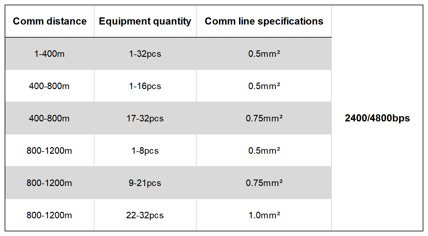
RVSP shielded twisted pair must be used. The specification of shielded twisted pair used is related to the distance of 485 communication line and the number of equipment connected, as shown in the following table. The use of shielded twisted pair helps to reduce and eliminate the distributed capacitance between the two 485 communication lines and the common mode interference from the communication line.

Someone say that 485 bus can communicate with 128 devices. In fact, not all 485 converters can be equipped with 128 devices. It should be judged according to the model of the chip in the 485 converter and the model of the chip in the 485 device. The load capacity can only be determined according to the chip with lower index. Generally, the load capacity of 485 chips has three levels: 32, 128 and 256. The longer the communication distance, the higher the baud rate, the thinner the wire diameter, the worse the wire quality, the worse the converter quality, the insufficient power supply of the converter (passive converter) and the stronger the lightning protection will reduce the real load.
Most engineering companies are accustomed to using class 5 or super class 5 network cable as 485 communication line, which is wrong. This is because:
(1) Common network cable has no shielding layer, which can not prevent common mode interference.
(2) It is not allowed to use the network cable with too thin wire diameter, which will reduce the transmission distance and the number of devices that can be connected. At least 0.4mm2 or standard network cable shall be used.
(3) The network wire is single strand copper wire, which is easier to break than multi-core wire.
4. Why grounding
The 485 transceiver can work normally when the specified common-mode voltage is between -7V and +12V. If it exceeds this range, the communication will be affected, and the communication interface will be damaged severely. Common-mode interference will increase the above-mentioned common-mode voltage. One of the effective ways to eliminate common mode interference is to use the shielding layer of the 485 communication line as a ground wire, connect the equipment in the network such as machines and computers together, and reliably connect them to the ground from one point.
5. How to route the 485 communication wire
The communication wire should be kept away from interference sources such as high-voltage wires and fluorescent lamps as far as possible. When the communication wire cannot be avoided from interference sources such as power wires, the communication wire should be vertical to the power line, not parallel, and cannot be bundled together, and use high-quality twisted-pair wires.
6. Can there be contact points between devices on the 485 bus?
In the same network system, use the same kind of cable to minimize the contact points in the line. Ensure that the joints are well welded and wrapped tightly to avoid looseness and oxidation. Ensure a single, continuous signal channel as the bus.
7. What is common mode interference and differential mode interference? How to eliminate the interference on the communication line?
The 485 communication line is composed of two twisted-pair lines. It transmits signals through the voltage difference between the two communication lines, so it is called differential voltage transmission. Differential mode interference is transmitted between two signal lines and belongs to symmetrical interference. The method to eliminate differential mode interference is to add a bias resistor (matching resistance in the ball machine) to the circuit, and use twisted pair; common mode interference is transmitted between the signal line and the ground, which is asymmetrical interference. Methods to eliminate common mode interference include:
(1) Use shielded twisted-pair wire and effectively ground it.
(2) Where the electric field is strong, galvanized pipes for shielding should also be considered to use.
(3) When wiring, keep away from high-voltage lines, and do not bundle high-voltage power lines and signal lines together.
(4) Use linear regulated power supply or high-quality switching power supply (ripple interference is less than 50mV).
Copyright © 2019.Company Name All Rights Reserved.