.png?v=v1)
.png?v=v1)
Metro is one of the main places of public gathering in modern cities. Once fire happens, it may bring great difficulties to safe evacuation of person in distress and timely rescue of firefighters, which may have a serious effect on the security of citizens’ lives and state property, thus it is necessary to strengthen the safety management of the fire control at metro public gathering places. According to the statistics, among metro fires both at home and abroad, fire accidents caused by electric account for the largest share of fire accidents, up to 37%. Leakage current of power supply line is the main cause of electrical fire.
As the subsystem of automatic fire alarm system (FAS), electrical fire monitoring system is mainly in charge of monitoring and alarming fires which may be caused by power system itself prior to fire. According to the regulations of JGJ 243-2011 Code for Electrical Design of Transportation Buildings, protected objects in case of fire in underground station of urban rail transit are Grade Ⅰ, so electrical fire monitoring system shall be set. It is required that electrical fire monitoring system shall be set during the fire control acceptance and expert review of urban rail transit all over the country at present.

GB 50157-2013 Code for Design of Metro
GB 50116-2013 Code for Design of Automatic Fire Alarm System
JGJ 243-2011 Code for Electrical Design of Transportation Buildings
GB 14287.1-2014 Electrical Fire Monitoring System - Part 1: Electrical Fire Monitoring Equipment
GB 14287.2-2014 Electrical Fire Monitoring System - Part 2: Residual Current Electrical Fire Monitoring Detectors
GB 14287.3-2014 Electrical Fire Monitoring System - Part 3: Temperature Sensing Electrical Fire Monitoring Detectors
In principle residual current electrical fire monitoring detectors are set at the head terminal of low-voltage distribution system, they shall be set at the outlet terminal of first-level power distribution cabinet (box). When the leakage current of power supply line is greater than 500 mA, residual current electrical fire monitoring detectors shall be set on the power distribution cabinet (box) of next level.
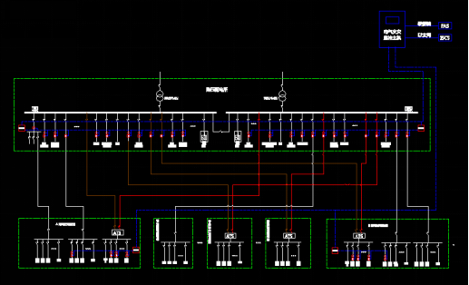
As for power supply system of metro, residual current detectors shall be set in the feeder circuit of 400 V switch cabinet in step-down substation and feeder circuit of environmental control fan in environmental control electrical control room, and temperature sensing detectors shall be subject to corresponding set. Currently, electrical fire monitoring system is set according to the station. Due to the combined setting of fire control room and train control room in metro station, corresponding monitoring hosts are set in train control rooms and at the same time, communication interfaces such as hard wiring interfaces and RJ45 are respectively reserved for FAS and integrated supervisory and control system in the metro station on monitoring hosts to realize the uploading of monitoring information of system.
In the configuration proposal of our company, alarm information and parameters are uploaded to monitoring unit and electrical fire monitoring equipment (hereinafter referred to as “monitoring host”) by residual current detectors and temperature sensing detectors via two-line bus for fire control. Two-line bus for fire control is characterized by long effective communication distance, flexible wiring and non-polarity, supporting star topology, tree topology and bus type topology, thus power supply line and signal line are combined as one to save cost on construction, maintenance and cables.
Application | Recommended Products | Model | Main Functions |
Train control room or equipment room in metro station |
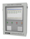
SCK680-BD electrical fire monitoring equipment (host) | ◆ Characterized by wall-mounted installation, liquid crystal display and friendly human machine interface. ◆ Realize real-time monitoring of data on the detector, timely alarm and unified management. ◆ Support the communication function with FAS、ISCS in the metro station.
| |
400 V switch cabinet and environmental control cabinet | SCK630 electrical fire monitoring unit | ◆Realize local monitoring in small area and parameter setting ◆Unify and upload data in small area to monitoring host ◆Isolate the bus | |
SCK630D electrical fire monitoring unit | ◆Realize local monitoring in small area and parameter setting ◆Unify and upload data in small area to monitoring host ◆Isolate the bus ◆ Characterized by guide rail type installation and self-contained 12 circuits for temperature measuring | ||
SCK600Y Integrated residual current electrical fire monitoring detector | ◆Monitor the residual current of 1 circuit ◆Adopt the two-line bus for fire control which is characterized by non-polarity, no auxiliary power supply and bus power for communication.
| ||
 | SCK600YT temperature sensing electrical fire monitoring detector | ◆Monitor the temperature of 4 circuits ◆Adopt the two-line bus for fire control which is characterized by non-polarity, no auxiliary power supply and bus power for communication.
|
Brief introduction of system function:
Monitoring host can realize the handling, alarm, control, statistics, management and communication of signal of each feeder circuit and can upload alarm information and real-time information of temperature/residual current to integrated supervisory and control system via RJ45 interface. Electrical fire monitoring equipment can receive clock synchronization signal (correct its own clock signal) from the integrated supervisory and control system and commands such as host reset. At the same time, the monitoring host can transmit fire alarm signal from important equipment to FAS system monitoring module via relay output interface and can link special firefighting equipment via automatic fire alarm controller in FAS system.
Real-time monitoring:
The system monitors real-time residual current and temperature of each circuit, and displays specific description and number of circuit and various function buttons on main interface.
Alarm display:
When the monitoring equipment system detects that residual current or temperature over-limit alarm occurs in any detector on site, corresponding circuit position on the monitoring interface will be shown in red, and immediately, a prompt message box will be popped up automatically on which all existing alarm information at present is displayed.
Historical records inquiries:
The monitoring equipment automatically records the off-limit alarms and equipment faults, and all the alarm (or fault) records may be accessed through the interface with button “Alarm record” (or “Fault record”) in operating area and records in specified row in reports can be printed out
Display of status information:
The main interface displays the current alarm in real time, and status lamp on the panel indicates the current system status.
User level management:
The monitoring equipment system provides three-level permissions (low-level permission, advanced permission and administrator permission). After the system is started, login without permission is allowed. (manual silencing operation can be performed in the case of no permission)
4.1 Configuration scheme for monitoring unit in single cabinet
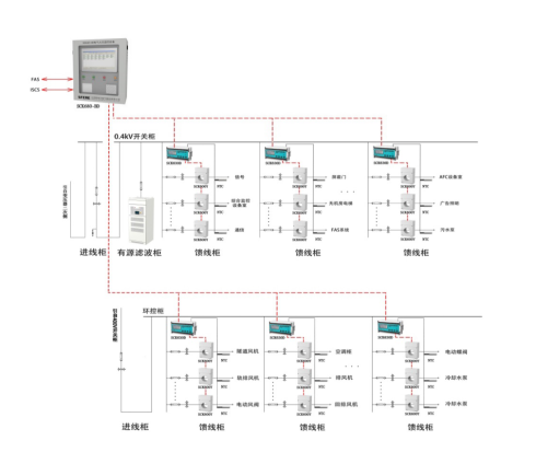
Single cabinet is equipped with one SCK630D monitoring unit for centralized monitoring on residual current detector and temperature sensing detector in the cabinet and for uploading of alarm information. The setting of the monitoring unit provides convenience for user to carry out operation and maintenance in the future and for the delivery inspection by complete equipment manufacturer. Simultaneously, the monitoring unit has the function of bus isolator, effectively isolating the faulted communication bus and ensuring the normal operation of other equipment.
The setting of detector is based on the number of monitoring circuits, with SCK600Y integrated residual current detector and NTC temperature sensor adopted. SCK600Y in the cabinet is connected to the downlink communication port of the monitoring unit with a fire-control two-line bus (supporting star topology, tree topology, and bus topology), and the NTC temperature sensor is directly connected to the temperature measuring terminal of monitoring unit.

Switch cabinet Incoming cabinet Active filtering cabinet Feeder cabinet Environment control cabinet

The uplink communication port of the monitoring unit of this cabinet is wired to the terminal block of this cabinet, which wiring to monitoring host in metro control room will be carried out together with the monitoring unit of other power distribution cabinets in unified method in site construction stage. For the scheme, a wall-mounted type monitoring host is adopted with small size, which is especially suitable for the use in places with limited space such as the station metro control room. The monitoring host provides the hardwire interface for the station FAS system, and RJ45 communication interface for the station integrated monitoring system, so as to realize the uploading of the system monitoring information.
Scheme characteristics:
1. Fully monitor the residual current and temperature of the related feeder circuits of 400V switch cabinet and environment control cabinet, with flexible configuration.
2. SCK630D electrical fire monitoring unit supports the measuring of 12-circuit temperature.
3. Use SCK600Y integrated residual current detector for electrical fire monitoring, with residual current value transmitted through the two-line bus, effectively avoiding the measurement errors caused by electromagnetic interference, as well as effectively improving the efficiency of operation and maintenance.
4. The monitoring host is equipped with backup power supply, printer, 2 relay outputs and a RJ45 communication interface.
4.2 Centralized configuration scheme for monitoring unit
For each 400V incoming cabinet, 2 or 3 SCK630 monitoring units shall be set in centralized method (screen installation). A total of 64~96 parameters can be monitored. The monitoring unit of environmental control electric control room is set in a environment control cabinet with a large screen surface, and usually, one SCK630 monitoring unit is suitable for the monitoring of 32 parameters.
The detector is based on the number of monitoring circuits, with SCK600Y integrated residual current detector and SCK600YT temperature sensing detector adopted. SCK600Y and SCK600YT in 400V feeder cabinet of the same bus section are connected to the downlink communication ports of the monitoring unit of incoming cabinet with shielded twisted pair (supporting star topology, tree topology, and bus topology). SCK600Y and SCK600YT in environment control cabinet are closely connected to the downlink communication ports of monitoring unit with shielded twisted pair.
A power distribution cabinet for monitoring unit shall be set, and the uplink communication port of its monitoring unit is wired to the terminal block of this cabinet, which wiring to monitoring host in metro control room will be carried out in unified method in site construction stage. For the scheme, a wall-mounted type monitoring host is adopted with small size, which is especially suitable for the use in places with limited space such as the station metro control room. The monitoring host provides the hardwire interface for the station FAS system, and RJ45 communication interface for the station integrated monitoring system, so as to realize the uploading of the system monitoring information.
Scheme characteristics:
1. Fully monitor the residual current and temperature of the related feeder circuits of 400V switch cabinet and environment control cabinet.
2. Use SCK600Y integrated residual current detector for electrical fire monitoring, with residual current value transmitted through the two-line bus, effectively avoiding the measurement errors caused by electromagnetic interference, as well as effectively improving the efficiency of operation and maintenance.
SCK680-B electrical fire monitoring equipment:

Application scenarios:
Station metro control room
Functions:
Monitoring alarm, fault alarm, self-inspection, information display and inquiry
Characteristics:
l Provide early predictive warning and emergency alarm on the monitored circuits, to timely eliminate the fire hazards and resolve the possible fire in the bud.
l Support Chinese Input and prompt of detector position in Chinese;
l The bus can directly supply the power to the bus-based electrical fire detectors;
l Set three-level permission to facilitate management;
l Support 2 relay outputs in fixed operating mode: The first output is alarm output, and the second is fault output.
l With backup power supply, support 4-hour continuous power supply.
l Provide hardwire interface for the station FAS system, and RJ45 communication interface for the station integrated monitoring system.
SCK630 electrical fire monitoring unit:

Application scenarios:
400V switch cabinet
Environmental control electric control cabinet.
Functions:
Monitoring, alarm and communication in small area
Characteristics:
l Adopt industrial graphic lattice LCD;
l Support Chinese Input and prompt of detector position in Chinese;
l Adopt non-polar and two-wire bus for simple and convenient wiring;
l The bus can directly supply the power to the bus-based electrical fire detectors;
l Set two-level permission to facilitate management;
l Support real-time monitoring for accurate positioning of alarm information;
SCK630D electrical fire monitoring unit:

Application scenarios:
400V switch cabinet
Environmental control electric control cabinet.
Functions:
Monitoring, alarm and communication in small area
Characteristics:
l Adopt industrial graphic lattice LCD;
l Support Chinese Input and prompt of detector position in Chinese;
l Adopt non-polar and two-wire bus for simple and convenient wiring;
l The bus can directly supply the power to the bus-based electrical fire detectors;
l Set two-level permission to facilitate management;
l Support real-time monitoring for accurate positioning of alarm information;
l 12-circuit temperature measurement
SCK600Y residual current electrical fire monitoring detector:

Application scenarios:
400V feeder circuit
Feeder circuit of environment control cabinet
Function:
Measure the residual current, and upload the data to monitoring unit or host.
Characteristics:
l Adopt non-polar two-wire connection and power supply of bus for simple and convenient wiring on the site.
l Realize unified address coding and alarm value setting with the monitoring equipment, to facilitate engineering commissioning and maintenance.
l Strong anti-interference capability of bus, with communication distance ≤1500m.
l The detector is provided with fault alarm light to facilitate troubleshooting of faults.
l Alarm threshold value of residual current sensor: 50-1000mA.
● Various types of residual current sensors and convenient installation.
SCK600YT temperature sensing electrical fire monitoring detector:

Application scenarios:
400V feeder circuit
Environment control feeder circuit
Function:
Measure temperature, and upload the data to monitoring unit or host.
Characteristics:
l Adopt non-polar two-wire connection and power supply of bus for simple and convenient wiring on the site.
l Realize unified address coding and alarm value setting with the monitoring equipment, to facilitate engineering commissioning and maintenance.
l Strong anti-interference capability of bus, with communication distance ≤1500m.
l The detector is provided with fault alarm light to facilitate troubleshooting of faults.
l Alarm threshold value of sensor: 55℃-140℃.
NTC temperature sensor

SCK600YT:
Application scenarios:
Cable joint on 400V feeder circuit
Cable joint on environment control feeder circuit
Functions:
Measure temperature and use with SCK600YT
Characteristics:
l By default, adopt Ф5*25 mm stainless steel protection tube, 1 meter with head twisted pair
l Precision: 1%, and temperature range: -10~150℃
l The user can customize the stainless steel protection tube, length of lead wire, and the specification of clamp, etc.
Copyright © 2019.Company Name All Rights Reserved.